ABSTRACT: We represent the magnetic field as a vector corresponding to the output of the sensor array.
In the previous page, we confirmed the principles of magnetoencephalography analysis.
In magnetoencephalography analysis, the current moment and position of the current dipole are estimated from the signals of the sensors (the sensor array).
Each sensor outputs signal as a scalar. Let the number of sensors be \(M\), and the signal output of the \(m\)th sensor be \({s}_{m}\). The signal output from the sensor array \( \boldsymbol{s} \) can be represented by a column vector as
$$ \boldsymbol{s}=\left(\begin{array}{cccc}s_{1} & s_{2} & \ldots & s_{M}\\\end{array}\right)^T $$
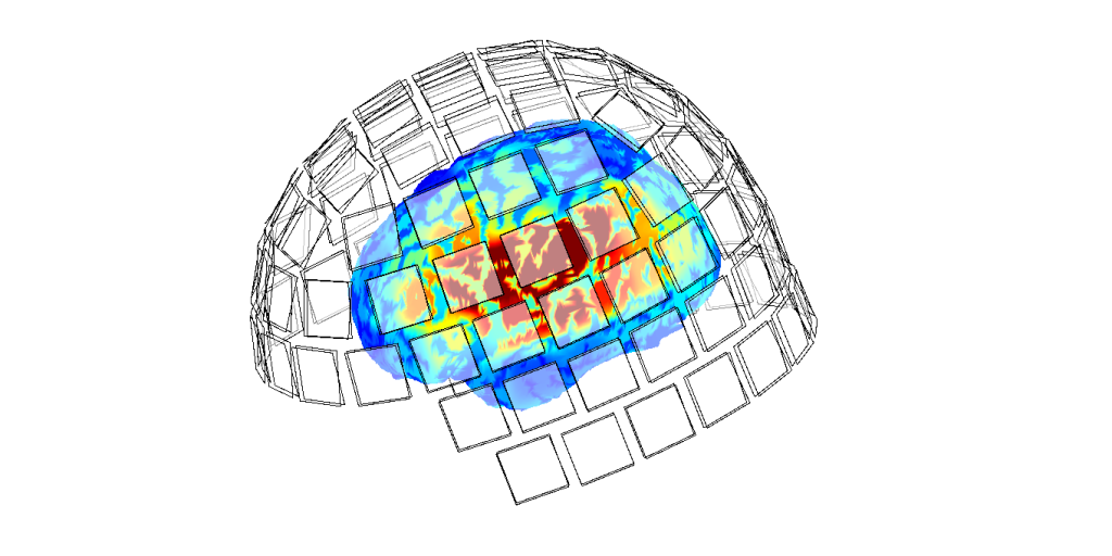
For example, the magnetoencephalograph TRIUX handled by the webmaster has 306 sensors (M = 306) because TRIUX has 102 pairs of squared sensors, each of which has one magnetometer and two planar gradiometers.

By the way, the magnetic field on the left side of the Sarvas formula \(\boldsymbol{b}(\boldsymbol{r})\) is a column vector with a three-dimension. On the other hand, the signal component of the sensor array \({s}_{m}\) is a scalar with a one-dimension. There is also a problem due to the shape of the sensor, whether it is a magnetometer or a planar gradiometer.
Therefore, it is necessary to examine how the sensor array responds to the current moment \(\boldsymbol{q}\) at the position of \(\boldsymbol{r}_{0}\).
In the following, we assume that the position of the current dipole is fixed at \(\boldsymbol{r}_{0}\).
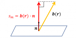
In the case of the sensor array consists of simple magnetometers are shown in the figure below. We can gain the signal \({s}_{m}\) by substituting the current moment \(\boldsymbol{q}\) and the position of each sensor (simply the center coordinate of the sensor \(\boldsymbol{r}\) ) for the Sarvas formula and extracting the component perpendicular to the sensor plane. In the calculation, we obtain the inner product of the result of the Sarvas formula and the unit normal vector of the sensor \(\boldsymbol{n}\). The unit in magnetoencephalography analysis is fT.

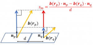
On the other hand, in the case of the sensor array consists of planar magnetometers are shown in the figure below. We can gain the signal \({s}_{m}\) as follows: First, to gain the differencing magnetic field \(\boldsymbol{b}_{q}\), substitute the current moment \(\boldsymbol{q}\) and the position of each differencing senosr \(\boldsymbol{r}_{q}\) for the Sarvas formula. Similary, the position of each differenced sensor \(\boldsymbol{r}_{p}\) produces the differenced magnetic field \(\boldsymbol{b}_{p}\). Next, find the inner product of each magnetic field and the unit normal vector of each sensor \(\boldsymbol{n}_{p}\), \(\boldsymbol{n}_{q}\). Then, Divide difference of these by the distance between the center of each sensor. The unit in magnetoencephalography analysis is fT/cm.

In this way, we can correspond the magnetic field of a three-dimensional vector \(\boldsymbol{b}(\boldsymbol{r})\) to the component of signal of the sensor array of as scholar \({s}_{m}\).
From now on, let us consider the magnetic field \(\boldsymbol{b}\) as the sensor array output of \(M\)-dimensional column vector \(\boldsymbol{s}\), which is discussed above. That is, when \(M\) is the number of sensors and the signal output of the \(m\)th sensor is \(b_{m}\), we represent the signal output from the sensor array \( \boldsymbol{b} \) as
$$ \boldsymbol{b}=\left(\begin{array}{cccc}b_{1} & b_{2} & \ldots & b_{M}\\\end{array}\right)^T $$
SUMMARY: We have represented the magnetic field as a column vector of corresponding number of dimension to number of output the sensor array.
In the next page, we will find \(\boldsymbol{L}\) using the linearity of the magnetic field to the current moment when the magnetic field \(\boldsymbol{b}\) is expressed as \(\boldsymbol{b}=\boldsymbol{L}\boldsymbol{q}\). This is called as Lead Feld Matrix (LFM), which is an indispensable concept for computationally processing the inverse problems.