Abstract: Non-adaptive beamformers include MNE, dSPM, sLORETA, SMF, etc.
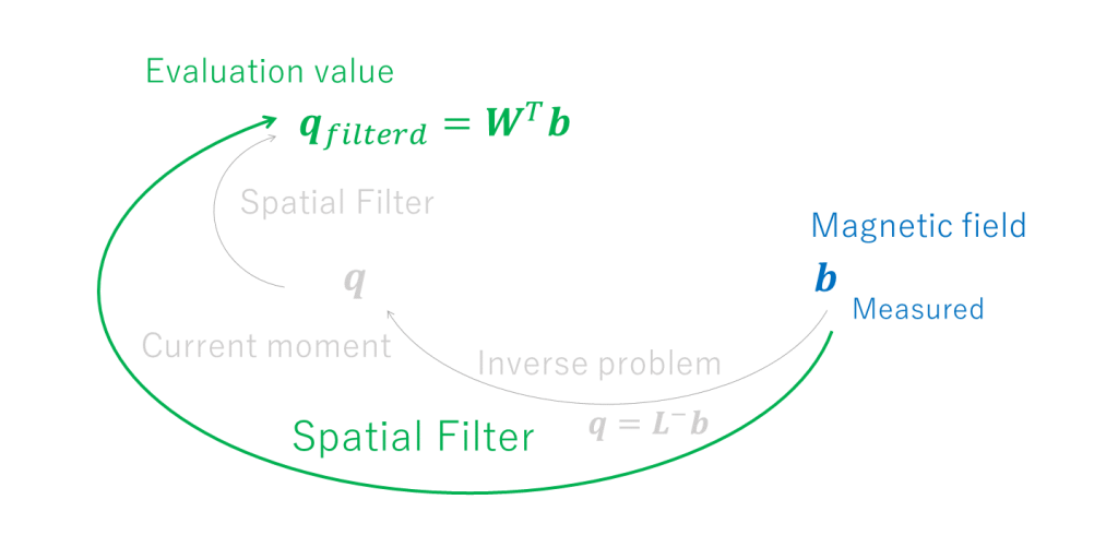
In the previous page, we started solving the inverse problem of the underdetermined system by finding the inverse linear mapping \( \boldsymbol{L}^{-} \) and determining the current moment \( \boldsymbol{q}\).
$$ \boldsymbol{q}=\boldsymbol{L}^-\boldsymbol{b} $$
The mathematical solution was the Minimum Norm Estimate (MNE) [1]. However, this did not fit the practice of magnetoencephalography analysis, so we extended the concept of solving the inverse problem to constructing the spatial filter.
Therefore, we intended to calculate the weighting matrix \(\boldsymbol{W}^{T}\) and determine the evaluation value \(\boldsymbol{q}_{filtered}\).
$$ \boldsymbol{q}_{filtered}= \boldsymbol{W}^T\boldsymbol{b} $$
From the previous page, the followings hold for MNEs:
$$ \boldsymbol{q}_{MNE}= \boldsymbol{q}=\boldsymbol{L}^T(\boldsymbol{L}\boldsymbol{L}^{T})^{-1}\boldsymbol{b} $$
$$ \boldsymbol{W}^{T}=\boldsymbol{W}_{MNE}^{T}= \left(\begin{array}{cccc} \boldsymbol{L}_{1}^T(\boldsymbol{L}\boldsymbol{L}^{T})^{-1} \\ \vdots \\ \boldsymbol{L}_{N}^T(\boldsymbol{L}\boldsymbol{L}^{T})^{-1} \end{array} \right) =\boldsymbol{L}^T(\boldsymbol{L}\boldsymbol{L}^{T})^{-1} $$
The MNE requires the overall signal as small as possible during the derivation process. Therefore, the obtained solution explains the sensor signal only by the lattice points close to the sensors. In other words, the current moment at the lattice points close to the sensors is relatively emphasized [2].
The distribution of MNE solutions is determined by the following relationship, as discussed in the previous page:
$$ \frac{\|\boldsymbol{q}_{n}\|}{\|\boldsymbol{b} \|} \leq \| \boldsymbol{L}_{n}^T(\boldsymbol{L}\boldsymbol{L}^{T})^{-1}\|_{F} $$
To normalize the maximum value, we divide the current moment by the right side to create a new evaluation value. This technique is known as Dynamic statistical parametric mapping (dSPM) or Weight (noise) normalized minimum norm filter [3].
We introduce
$$ \boldsymbol{q}_{n_{MNE}}=\boldsymbol{q}_{n} $$
$$ \boldsymbol{q}_{n_{dSPM}}=\frac{\boldsymbol{q}_{n_{MNE}}}{\| \boldsymbol{L}_{n}^T(\boldsymbol{L}\boldsymbol{L}^{T})^{-1}\|_{F}} $$
And it holds
$$ \boldsymbol{q}_{n_{dSPM}}=\frac{\boldsymbol{L}_{n}^T(\boldsymbol{L}\boldsymbol{L}^{T})^{-1}\boldsymbol{b}}{\| \boldsymbol{L}_{n}^T(\boldsymbol{L}\boldsymbol{L}^{T})^{-1}\|_{F}}=\frac{\boldsymbol{L}_{n}^T(\boldsymbol{L}\boldsymbol{L}^{T})^{-1}\boldsymbol{b}}{\sqrt{tr(\boldsymbol{L}_{n}^{T}(\boldsymbol{L}\boldsymbol{L}^{T})^{-2}\boldsymbol{L}_{n})}} $$
The relationship is
$$ \frac{\| \boldsymbol{q}_{n_{dSPM}} \|}{\| \boldsymbol{b} \|}=\frac{\| \boldsymbol{L}_{n}^T(\boldsymbol{L}\boldsymbol{L}^{T})^{-1}\boldsymbol{b}\|}{\| \boldsymbol{L}_{n}^T(\boldsymbol{L}\boldsymbol{L}^{T})^{-1}\|_{F} \| \boldsymbol{b} \|} \leq \frac{\| \boldsymbol{L}_{n}^T(\boldsymbol{L}\boldsymbol{L}^{T})^{-1}\|_{F}\|\boldsymbol{b}\|}{\| \boldsymbol{L}_{n}^T(\boldsymbol{L}\boldsymbol{L}^{T})^{-1}\|_{F} \| \boldsymbol{b} \|}=1 $$
Now, the evaluation value of each grid point does not depend on the position, and the maximum value (relative to the magnitude of the magnetic field) is standardized to 1. If the weight matrix in this case is expressed as \(\boldsymbol{W}_{dSPM}^{T}\), then
$$ \boldsymbol{W}_{dSPM}^{T}= \left(\begin{array}{cccc} \frac{\boldsymbol{L}_{1}^T(\boldsymbol{L}\boldsymbol{L}^{T})^{-1}}{\sqrt{tr(\boldsymbol{L}_{1}^{T}(\boldsymbol{L}\boldsymbol{L}^{T})^{-2}\boldsymbol{L}_{1})}} \\ \vdots \\ \frac{\boldsymbol{L}_{N}^T(\boldsymbol{L}\boldsymbol{L}^{T})^{-1}}{\sqrt{tr(\boldsymbol{L}_{N}^{T}(\boldsymbol{L}\boldsymbol{L}^{T})^{-2}\boldsymbol{L}_{N})}} \end{array} \right) $$
Athough it seems like everything is fine, it is well known that the solution from dSPM does not match the signal source positionally even in the absence of noise (the position bias) [2]. We should take care when using it.
Note that the units of the dSPM evaluation value \(\boldsymbol{q}_{dSPM}\) are fT or fT/cm from the above equation, which are the same as the units of the sensor output.
By the way, \( (\boldsymbol{L}\boldsymbol{L}^{T})^{-2} \) in the root of the denominator does not depend on the position of the lattice point, and the evaluation value \(\boldsymbol{q}_{filtered}\) does not concern the actual current moment but the relative signal strength at each lattice point. Therefore, we can consider a method to reduce the amount of calculation by omitting \( (\boldsymbol{L}\boldsymbol{L}^{T})^{-2} \).
The next method is a reduction of the order of \( (\boldsymbol{L}\boldsymbol{L}^{T})^{-2} \) in the root of the denominator of dSPM, and is called Standardized Low-resolution Tomography (sLORETA) [4].
$$ \boldsymbol{q}_{n_{sLORETA}}=\frac{\boldsymbol{q}_{n_{MNE}}}{\sqrt{tr(\boldsymbol{L}_{n}^{T}(\boldsymbol{L}\boldsymbol{L}^{T})^{-1}\boldsymbol{L}_{n})}}=\frac{\boldsymbol{L}_{n}^T(\boldsymbol{L}\boldsymbol{L}^{T})^{-1}\boldsymbol{b}}{\sqrt{tr(\boldsymbol{L}_{n}^{T}(\boldsymbol{L}\boldsymbol{L}^{T})^{-1}\boldsymbol{L}_{n})}} $$
$$ \boldsymbol{W}_{sLORETA}^{T}= \left(\begin{array}{cccc} \frac{\boldsymbol{L}_{1}^T(\boldsymbol{L}\boldsymbol{L}^{T})^{-1}}{\sqrt{tr(\boldsymbol{L}_{1}^{T}(\boldsymbol{L}\boldsymbol{L}^{T})^{-1}\boldsymbol{L}_{1})}} \\ \vdots \\ \frac{\boldsymbol{L}_{N}^T(\boldsymbol{L}\boldsymbol{L}^{T})^{-1}}{\sqrt{tr(\boldsymbol{L}_{N}^{T}(\boldsymbol{L}\boldsymbol{L}^{T})^{-1}\boldsymbol{L}_{N})}} \end{array} \right) $$
The unit of the evaluation value of sLORETA, \(\boldsymbol{q}_{sLORETA}\), is Am from the above equation, which is the same as the current moment.
Furthermore, the next method completely omits \( (\boldsymbol{L}\boldsymbol{L}^{T})^{-2} \) in the root of the denominator of dSPM and also omits \( (\boldsymbol{L}\boldsymbol{L}^{T})^{-1} \) in the numerator, and is called the Spatial Matched Filter (SMF) [2].
$$ \boldsymbol{q}_{n_{SMF}}=\frac{\boldsymbol{L}_{n}^{T}\boldsymbol{b}}{\|\boldsymbol{L_{n}}\|_{F}}=\frac{\boldsymbol{L}_{n}^{T}\boldsymbol{b}}{\sqrt{tr(\boldsymbol{L}_{n}^{T}\boldsymbol{L}_{n})}} $$
$$ \boldsymbol{W}_{SMF}^{T}= \left(\begin{array}{cccc} \frac{\boldsymbol{L}_{1}^{T}\boldsymbol{b}}{\sqrt{tr(\boldsymbol{L}_{1}^{T}\boldsymbol{L}_{1})}} \\ \vdots \\ \frac{\boldsymbol{L}_{N}^{T}\boldsymbol{b}}{\sqrt{tr(\boldsymbol{L}_{N}^{T}\boldsymbol{L}_{N})}} \end{array} \right) $$
The units of the SMF evaluation value \(\boldsymbol{q}_{SMF}\), like that of dSPM, are fT or fT/cm, which are the same as the units of the sensor output.
An interesting point about SMF, which is different from dSPM and sLORETA, is that \(\boldsymbol{q}_{n_{SMF}}\) cannot be directly expressed by \(\boldsymbol{q}_{n_{MNE}}=\boldsymbol{q}_{n}\) (although it can be expressed by over-regularization). In the end, what is important in spatial filtering is only to discuss and propose the weight matrix \(\boldsymbol{W}^{T}\) and to construct the evaluation value \(\boldsymbol{q}_{filtered}\). There is no longer any interest in MNE, which is a mathematically underdetermined solution, and there is no need to reconstruct the estimation result by a forward problem as in the case of overdetermined solutions. Therefore, constructing a spatial filter is synonymous with solving an inverse problem (see figure below).

By the way, in terms of solution-source consistency, sLORETA and SMF are known to have no position bias in the absence of noise [2]. For reasons described below, the webmaster prefers sLORETA.
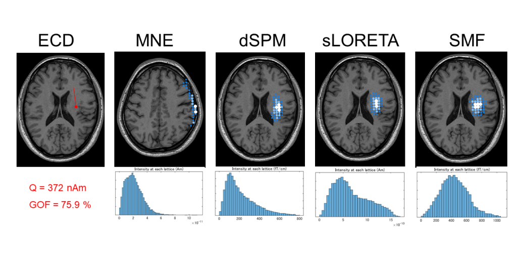
For reference, the results of an analysis of the webmaster’s physiological waveform (probably mu rhythm judging from the behavior of the EEG) are shown in the following order: Equivalent Current Dipole (ECD), MNE, dSPM, sLORETA, and SMF.

The spatial filters excluding ECD in the upper row show the top 100 signal intensities (magnitude of current moment) for N=14,000 grid points, and the lower row shows a histogram of signal intensities. In fact, the analysis results on the image are almost the same except for MNE. However, the signal intensity distribution is gradually becoming less skewed.
If we assume that the more right-skewed signal intensity distribution (the stronger the signal, the steeper the number of grid points that belong to it) is the more desirable, the order is MNE > dSPM > sLORETA > SMF empirically and literaturely [2]. The amount of calculation required to construct the spatial filter is also dSPM > sLORETA > SMF (although the calculation time is not so long and the results can be applied to the same case repeatedly).
The magnitude of the evaluation values for SMF & dSPM vs. sLORETA & MNE differers significantly, but this is due to difference of the units.
Spatial filters are very flexible and physiological because they assume that signals are generated throughout the entire signal space (the entire brain in magnetoencephalography).
On the other hand, the number of dimensions of the current moment 2N (20,000) generated by the grid points is much larger than the number of sensor signals M (=204 or 306), which means that high spatial accuracy cannot be expected. Given this premise, it can be interpreted that it is unreasonable to expect both a skewed distribution and no positional bias.
The type of spatial filter to be used depends on the situation and the examiner’s preference, and if the results vary significantly depending on the filter, the sample analyzed may not be good.
This is a matter of personal preference, but the webmaster prefers to use the non-adaptive beamformer sLORETA as a spatial filter. The reasons are as follows:
- It requires a moderate amount of calculation and is stress-free.
- The unit of each evaluation value is the same as the current moment.
- The skewness is relatively gentle, so the position of the current source is not excessively restricted. [2]
- If there is no noise, the solution positionally matches the signal source (there is no position bias). [2]
- Unlike the Adaptive Beamformer, the results do not differ depending on the time width.
Summary: Various proposals have been made for non-adaptive beamformers, but each has its own advantages and disadvantages, and it is necessary to be familiar with the characteristics of each when operating them.
Now we have reached the limitations of the discussion of non-adaptive beamformers. In the next page, we would like to consider adaptive beamformers.
(References)
- MS Hämäläinen, RJ Ilmoniemi: Interpreting magnetic fields of the brain: minimum norm estimates. Med Biol Eng Comput. 1994 Jan;32(1):35-42.
- Kensuke Sekihara, Maneesh Sahani, Srikantan S Nagarajan: Localization bias and spatial resolution of adaptive and non-adaptive spatial filters for MEG source reconstruction. Neuroimage. 2005 May 1;25(4):1056-67.
- AM Dale, AK Liu, BR Fischl, RL Buckner, JW Belliveau, JD Lewine, E Halgren: Dynamic statistical parametric mapping: combining fMRI and MEG for high-resolution imaging of cortical activity. Neuron. 2000 Apr;26(1):55-67.
- RD Pascual-Marqui: Standardized low-resolution brain electromagnetic tomography (sLORETA): technical details. Methods Find Exp Clin Pharmacol. 2002;24 Suppl D:5-12.